IP Networking Fundamentals
IP Networking Fundamentals
Understanding how devices communicate across networks requires breaking down a complex process into manageable components. This section covers the foundational concepts of client-server communication, the TCP/IP protocol stack, and how data flows through a network.
Client-Server Roles
Network communication is built on the relationship between clients and servers. These are roles, not permanent identities, a single device can act as both depending on the current activity.
Role Definitions
| Role | Function | Example |
|---|---|---|
| Client | Requests a service or resource | A browser requesting a webpage |
| Server | Provides a service or resource | A web server responding with HTML content |
Role Flexibility
A single device can operate in multiple roles simultaneously. Consider a web server that requires authentication:
- The client browser sends credentials to the web server
- The web server, acting as a client, queries a database server to verify those credentials
- The database server, acting as a server, responds with authentication results
Client Browser → [requests webpage] → Web Server (acting as server)
                   ↓
Web Server → [queries credentials] → Database Server (acting as client to DB)
This demonstrates that client and server are roles based on current activity, not fixed device identities.
Network Communication Models
Communicating across a network involves dozens of protocols, services, and hardware interactions. Managing this complexity requires breaking it into logical layers.
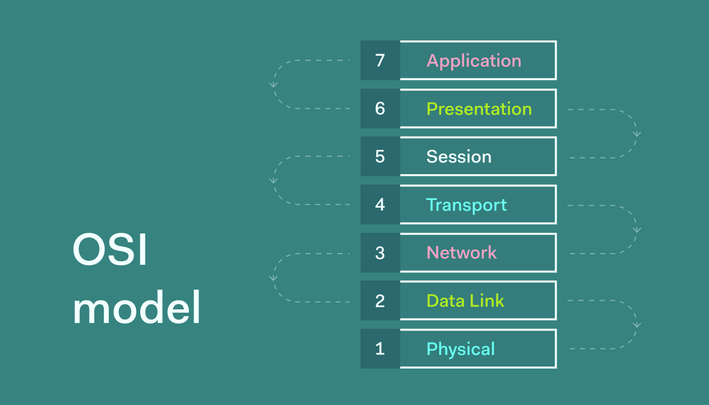
The OSI Reference Model
The Open System Interconnection (OSI) model was created in the 1970s by the International Organization for Standardization (ISO). It provides a seven-layer framework for understanding network communication.
The TCP/IP Protocol Stack
The TCP/IP Protocol Stack (also called the TCP/IP Protocol Suite) is what networks actually use today, including the internet. The OSI model is a reference framework, TCP/IP is the implementation.
The Hybrid Model Used Today
In practice, the networking industry uses a hybrid approach: we use the TCP/IP Protocol Stack but borrow layer numbers and names from the OSI model when describing it.
TCP/IP Stack          OSI Model              Hybrid (Used in Practice)
─────────────        ─────────              ─────────────────────────
Application          7 - Application        Application Layer (no number)
                     6 - Presentation
                     5 - Session
Transport            4 - Transport          Layer 4 - Transport
Internet             3 - Network            Layer 3 - Network
Network Access       2 - Data Link          Layer 2 - Data Link
                     1 - Physical           Layer 1 - Physical
Key takeaway: When someone references “Layer 3” or “Layer 2” in networking, they’re referring to this hybrid model, not strictly OSI or strictly TCP/IP.
Layer Breakdown
Application Layer
The application layer represents network services and functions requested by users or applications. This does not mean the application itself, but the protocol that application uses to communicate.
| Protocol | Full Name | Function |
|---|---|---|
| HTTP | Hypertext Transfer Protocol | Delivers web pages |
| HTTPS | HTTP Secure | Encrypted web page delivery |
| DNS | Domain Name System | Translates domain names to IP addresses |
| DHCP | Dynamic Host Configuration Protocol | Assigns IP addresses automatically |
| FTP | File Transfer Protocol | Transfers files between systems |
| SMTP | Simple Mail Transfer Protocol | Sends email |
DNS in Practice
DNS functions like a phonebook for the internet. When a user types a domain name (e.g., example.com), DNS resolves it to an IP address that the computer can use for communication.
User types: example.com
    ↓
DNS query → DNS Server
    ↓
DNS response → 192.168.1.100
    ↓
Computer uses IP address for communication
Verification on Windows:
ipconfig /flushdns
ipconfig /displaydns
Transport Layer (Layer 4)
The transport layer defines how data is delivered between hosts. Each application layer protocol is associated with a specific transport layer protocol.
| Protocol | Full Name | Characteristics |
|---|---|---|
| TCP | Transmission Control Protocol | Reliable, connection-oriented, error-checked delivery |
| UDP | User Datagram Protocol | Fast, connectionless, no guaranteed delivery |
Application-to-Transport Mapping
| Application Layer Service | Transport Layer Protocol |
|---|---|
| HTTP / HTTPS | TCP |
| DNS | UDP |
| SMTP | TCP |
| FTP | TCP |
| DHCP | UDP |
Key point: Users don’t choose the transport layer protocol. Each application layer service has a predetermined association with its transport protocol.
Network Layer (Layer 3)
The network layer handles logical addressing and routing. The primary protocol is IP (Internet Protocol), which comes in two versions:
| Version | Format | Status |
|---|---|---|
| IPv4 | 32-bit, dotted decimal (e.g., 10.10.0.50) |
Current standard, widely deployed |
| IPv6 | 128-bit, hexadecimal (e.g., 2001:db8::1) |
Next generation, growing adoption |
IPv4 Address Structure
An IPv4 address contains two components, analogous to a physical mailing address:
| Component | Analogy | Example |
|---|---|---|
| Network address | Street name | 10.10.0 |
| Host address | House number | .50 |
Full address: 10.10.0.50
              ├───┬───┘ ├┘
              │       │   └─ Host (device on network)
              └───────┴─── Network (street)
Source and Destination Addresses
Every network communication includes:
- Source IP — the sender’s address (e.g.,
10.10.0.50) - Destination IP — the recipient’s address (e.g.,
10.20.0.100)
If the destination address is unknown, the client first performs a DNS lookup to resolve the domain name to an IP address.
Verifying local IP address on Windows:
ipconfigDefault Gateway
When a device needs to communicate with a device on a different network, it forwards traffic to its default gateway (a router). The router then forwards the traffic toward the final destination.
Client (10.10.0.50) → Default Gateway (10.10.0.1) → Router → Destination NetworkData Link Layer (Layer 2)
The data link layer handles physical addressing within a local network. Every network interface card (NIC) has a unique address burned in by the manufacturer.
Layer 2 Address Names
This single address has multiple names, all referring to the same thing:
| Name | Abbreviation | Context |
|---|---|---|
| Layer 2 Address | — | Protocol stack reference |
| Burned-In Address | BIA | Manufacturer-assigned |
| Physical Address | — | Hardware-based |
| Media Access Control Address | MAC | IEEE standard term |
| Ethernet Address | — | Ethernet-specific reference |
MAC Address Format
| Property | Value |
|---|---|
| Length | 48 bits (12 hexadecimal characters) |
| Format | XX:XX:XX:XX:XX:XX (e.g., 14:75:5B:67:83:10) |
| Uniqueness | Guaranteed unique by manufacturer |
| Assignment | First half = manufacturer ID (OUI), second half = device serial |
MAC Address Analogy
Think of a shared mailbox system:
Elm Street (Network 10.10.0.0)
├── House 51 (IP: 10.10.0.51) → Mailbox Slot 1 (MAC: AA:BB:CC:DD:EE:01)
├── House 52 (IP: 10.10.0.52) → Mailbox Slot 2 (MAC: AA:BB:CC:DD:EE:02)
└── House 53 (IP: 10.10.0.53) → Mailbox Slot 3 (MAC: AA:BB:CC:DD:EE:03)
The mail carrier delivers to the common mailbox area (switch) using the slot number (MAC address) to reach the correct house (IP address).
Layer 2 in Communication
Before sending data, a computer includes in the Layer 2 header:
- Source MAC address — the sender’s NIC address
- Destination MAC address — the next-hop device’s NIC address (e.g., default gateway)
Verifying MAC address on Windows:
ipconfig /allOr using ARP to view learned MAC addresses:
arp -aARP (Address Resolution Protocol): Translates Layer 3 IP addresses to Layer 2 MAC addresses. Think of it as “DNS for Layer 2.”
Physical Layer (Layer 1)
The physical layer represents the actual media and signals that transmit data across the network.
| Medium | Description |
|---|---|
| Copper (Ethernet) | Twisted pair cables (Cat5e, Cat6, Cat6a) |
| Fiber Optic | Light-based transmission over glass/plastic fiber |
| Wireless | Radio waves through air (Wi-Fi, Bluetooth) |
Data Encapsulation and De-encapsulation
Encapsulation (Sending)
As data moves down the protocol stack, each layer adds its own header information:
Application Data (HTTP request)
    ↓ + Layer 4 Header (TCP/UDP)
    ↓ + Layer 3 Header (IP addresses)
    ↓ + Layer 2 Header (MAC addresses)
    ↓ = Bits on the wire (Layer 1)
De-encapsulation (Receiving)
As data moves up the protocol stack at the destination, each layer strips its header:
Bits received (Layer 1)
    ↓ Read Layer 2 header → MAC address matches? → Process up
    ↓ Read Layer 3 header → IP address matches? → Process up
    ↓ Read Layer 4 header → Port/service identified → Process up
    ↓ Application data delivered to service
Protocol Data Units (PDUs)
Each layer has a specific term for the unit of data it handles:
| Layer | PDU Name | Contents |
|---|---|---|
| Layer 4 | Segment (TCP) / Datagram (UDP) | Transport header + data |
| Layer 3 | Packet | IP header + data |
| Layer 2 | Frame | MAC header + data + trailer |
| Layer 1 | Bits | Raw electrical/optical signals |
Practical note: In casual conversation, “packet” is often used generically to describe data at any layer. The technically correct terms above apply when precision matters.
Network Device Forwarding
Network devices use different header information for forwarding decisions:
| Device | Layer | Looks At | Forwarding Decision Based On |
|---|---|---|---|
| Switch | Layer 2 | MAC addresses | Destination MAC address |
| Router | Layer 3 | IP addresses | Destination IP address |
| Firewall | Layers 3-7 | IP, ports, application data | Security policies, ACLs, application rules |
Client → Switch (L2 forwarding) → Router (L3 forwarding) → Firewall (L3-7 inspection) → ServerPacket Capture Verification
Using Wireshark or similar tools, you can verify the protocol stack in action:
| Layer | Wireshark Display Filter | What You See |
|---|---|---|
| Application | dns or http |
DNS queries, HTTP requests/responses |
| Transport | tcp or udp |
Source/destination ports, sequence numbers |
| Network | ip or ip.addr == 10.10.0.50 |
Source/destination IP addresses |
| Data Link | eth or ether |
Source/destination MAC addresses |