Layer 2 Switching
Layer 2 Switching
Layer 2 switching is the process of forwarding data frames based on MAC (Media Access Control) addresses. A Layer 2 switch operates at the Data Link layer and makes forwarding decisions by examining the destination MAC address in the Layer 2 header.
Switch Fundamentals
What a Layer 2 Switch Does
A Layer 2 switch performs one primary function: forward frames between ports based on destination MAC addresses. It does not examine Layer 3 (IP) addresses, Layer 4 protocols or application layer data. Its decision-making is limited to the Data Link layer.
Client PC → Frame arrives at switch → Switch reads destination MAC → Forwards to correct portLayer 2 Header Contents
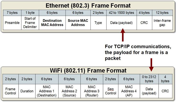
When a device prepares data for transmission, it includes Layer 2 information in the frame header:
| Field | Description |
|---|---|
| Source MAC Address | The sending device’s NIC address |
| Destination MAC Address | The next-hop device’s NIC address |
| Type/Length | Indicates the Layer 3 protocol encapsulated (e.g., IPv4, IPv6) |
| Frame Check Sequence (FCS) | Error detection via CRC calculation |
Key point: A Layer 2 switch only cares about MAC addresses. It doesn’t know or care about IP addresses, subnet masks, or routing tables.
MAC Address Table
The switch maintains a MAC address table (also called a CAM table) that maps MAC addresses to physical ports. This table is how the switch knows where to forward frames.
How the Switch Learns MAC Addresses
The switch builds its MAC address table dynamically by examining the source MAC address of every incoming frame:
- A frame enters the switch on a specific port
- The switch reads the source MAC address from the Layer 2 header
- The switch records: “This MAC address is reachable on this port”
- When a frame arrives with a known destination MAC address, the switch forwards it out the associated port
Frame arrives on Gig 0/2 with source MAC AAAA
    ↓
Switch records: AAAA → Gig 0/2
    ↓
Future frames destined to AAAA are forwarded out Gig 0/2
MAC Address Table Example
| MAC Address | Port | Learned From |
|---|---|---|
AA:BB:CC:DD:EE:01 |
Gig 0/0 | Router 1 sent a frame with this source MAC |
AA:BB:CC:DD:EE:02 |
Gig 0/1 | PC-10 sent a frame with this source MAC |
AA:BB:CC:DD:EE:03 |
Gig 0/2 | Client PC sent a frame with this source MAC |
Viewing the MAC address table on a Cisco switch:
show mac address-tableExample output:
Switch# show mac address-table
          Mac Address Table
-------------------------------------------
Vlan    Mac Address       Type        Ports
----    -----------       --------    -----
   1    aabb.ccdd.ee01   DYNAMIC     Gi0/0
   1    aabb.ccdd.ee02   DYNAMIC     Gi0/1
   1    aabb.ccdd.ee03   DYNAMIC     Gi0/2
Dynamic learning: The switch continuously relearns MAC addresses every time a frame arrives. If a device moves to a different port, the switch updates its table accordingly.
MAC Address Format
A MAC address address operates at Layer 2, every device has a unique identifier burned into its network interface card.
Address Properties
| Property | Value |
|---|---|
| Length | 48 bits (6 bytes) |
| Representation | 12 hexadecimal characters |
| Format | XX:XX:XX:XX:XX:XX or XXXX.XXXX.XXXX |
| Uniqueness | Guaranteed by manufacturer (theoretically globally unique) |
Address Structure
MAC Address: AA:BB:CC:DD:EE:FF
             ├───┬──┘ ├───┬──┘
             │       │      └─ Device serial (unique per NIC)
             │       └─ OUI (Organizationally Unique Identifier)
             └─ Manufacturer assigned
Common Names for Layer 2 Addresses
| Name | Context |
|---|---|
| MAC Address | Most common term (Media Access Control) |
| Physical Address | Hardware-based identifier |
| Burned-In Address (BIA) | Factory-assigned, permanent |
| Ethernet Address | Ethernet-specific reference |
| Hardware Address | Generic reference to NIC address |
Display Format Variations
Different systems display the same MAC address in different formats:
| System | Format | Example |
|---|---|---|
| Windows | XX-XX-XX-XX-XX-XX |
14-75-5B-67-83-10 |
| Cisco IOS | XXXX.XXXX.XXXX |
1475.5B67.8310 |
| Linux/Unix | XX:XX:XX:XX:XX:XX |
14:75:5B:67:83:10 |
Finding MAC address on Windows:
ipconfig /allFinding MAC address on a Cisco router:
show interface GigabitEthernet 0/0Look for the line: Hardware is ... , address is XXXX.XXXX.XXXX (bia XXXX.XXXX.XXXX)
ARP — Address Resolution Protocol
ARP resolves Layer 3 IP addresses to Layer 2 MAC addresses. It allows devices on the same local network to discover each other’s MAC addresses dynamically.
Why ARP Is Needed
When a device wants to communicate with another device on the same network, it knows the destination IP address (Layer 3) but needs the destination MAC address (Layer 2) to construct the frame. ARP provides this resolution.
Device knows: Destination IP address (Layer 3)
Device needs: Destination MAC address (Layer 2)
    ↓
Device uses ARP to ask: "Who has this IP address? What's your MAC address?"
    ↓
Owner responds: "I have that IP. Here's my MAC address."
    ↓
Device caches the result for future use
ARP Process
| Step | Action | Description |
|---|---|---|
| 1 | ARP Request | Broadcast to all devices on the local network: “Who has IP 10.10.0.51?” |
| 2 | ARP Reply | Unicast response from the owner: “I have 10.10.0.51. My MAC is AA:BB:CC:DD:EE:01” |
| 3 | Cache Entry | Requesting device stores the IP-to-MAC mapping in its ARP cache |
Client PC (10.10.0.50)
    ↓ ARP Request (broadcast): "Who has 10.10.0.51?"
    ↓
Switch forwards to all ports (broadcast)
    ↓
PC-10 (10.10.0.51) responds: "My MAC is 6668.00XX.XXXX"
    ↓
Client PC caches: 10.10.0.51 → 6668.00XX.XXXX
ARP Cache
Each device maintains an ARP cache — a table of recently resolved IP-to-MAC mappings.
Viewing ARP cache on Windows:
arp -aExample output:
Interface: 10.10.0.50
  Internet Address    Physical Address    Type
  10.10.0.1           00-1a-2b-74-00-08   dynamic
  10.10.0.51          00-1a-2b-66-68-00   dynamic
Clearing ARP cache on Windows (requires administrator):
arp -d *Viewing ARP cache on a Cisco router:
show arpExample output:
Protocol  Address          Age (min)  Hardware Addr   Type   Interface
Internet  10.10.0.1              -    aabb.cc74.0008  ARPA   GigabitEthernet0/0
Internet  10.10.0.50             3    aabb.cc67.8310  ARPA   GigabitEthernet0/0
Internet  10.10.0.51             5    aabb.cc66.6800  ARPA   GigabitEthernet0/0
Clearing ARP cache on a Cisco router (interface bounce):
configure terminal
interface GigabitEthernet 0/0
shutdown
no shutdown
end
Note: The first ping to a new destination often fails because ARP resolution is occurring. Subsequent pings succeed because the MAC address is now cached.
ARP in Packet Capture
Using Wireshark, ARP traffic is clearly visible:
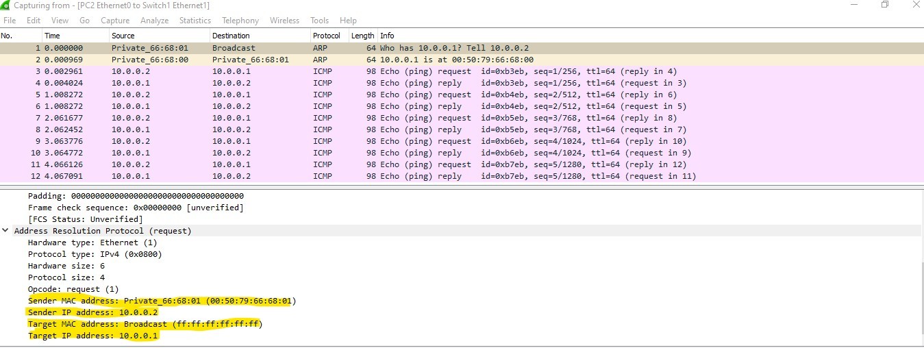
Wireshark display filter for ARP:
arpEthernet Standards and Switch Ports
Ethernet Speed Progression
| Standard | Speed | Common Name |
|---|---|---|
| Ethernet | 10 Mbps | Ethernet |
| Fast Ethernet | 100 Mbps | FE |
| Gigabit Ethernet | 1,000 Mbps (1 Gbps) | GigE |
| 10 Gigabit Ethernet | 10,000 Mbps (10 Gbps) | 10GbE |
| 40 Gigabit Ethernet | 40,000 Mbps (40 Gbps) | 40GbE |
Physical Port Types
| Port Type | Connector | Media | Typical Use |
|---|---|---|---|
| Ethernet | RJ45 | Copper (UTP) | End-user devices, short runs |
| SFP | LC (fiber) or RJ45 (copper) | Fiber optic or copper | Switch-to-switch uplinks, longer runs |
| SFP+ | LC (fiber) | Fiber optic | 10 Gbps uplinks |
| Console | RJ45 or USB | Serial cable | Initial configuration, management |
Cable Categories
| Category | Speed | Distance |
|---|---|---|
| Cat5e | Up to 1 Gbps | 100 meters |
| Cat6 | Up to 10 Gbps | 55 meters (10G), 100 meters (1G) |
| Cat6a | Up to 10 Gbps | 100 meters |
SFP Modules
Small Form-factor Pluggable (SFP) modules allow flexible media selection:
| Module | Speed | Supported | | :— | :— | | SFP | 1 Gbps | Copper or fiber optic | | SFP+ | 10 Gbps | Fiber optic (primarily) |
Console port usage:
USB on PC → Console Cable (USB-to-RJ45) → Console Port on Switch/Router
    ↓
Terminal emulation software (PuTTY, SecureCRT) for CLI access
Virtual Switch
Virtual switches provide Layer 2 switching functionality in virtualized environments without dedicated physical hardware:
| Environment | Virtual Switch Type |
|---|---|
| VMware vSphere | vSwitch, Distributed vSwitch (vDS) |
| Microsoft Hyper-V | Virtual Switch |
| AWS | Virtual Private Cloud (VPC) networking |
| Azure | Virtual Network (VNet) switching |
VMware vSwitch example:
Virtual Machines → Virtual Switch → Physical NICs (uplinks) → Physical NetworkVirtual machines communicating within the same virtual switch don’t require traffic to leave the host. The virtual switch handles Layer 2 forwarding internally.
Frame Forwarding Process
Complete Frame Journey
When a client PC sends data to a server on a different network:
1. Client PC constructs frame:
   - Layer 2: Source MAC (client) → Destination MAC (default gateway)
   - Layer 3: Source IP (client) → Destination IP (server)

2. Frame enters switch on Gig 0/2
   - Switch learns client's MAC from source field
   - Switch reads destination MAC (gateway's MAC)
   - Switch forwards frame out the port associated with gateway's MAC

3. Default gateway (router) receives frame:
   - Examines Layer 3 destination IP
   - Determines next hop toward destination network
   - Constructs new frame with appropriate Layer 2 addresses
   - Forwards toward destination
Switch vs Router Decision Making
| Device | Layer | Reads | Forwarding Decision Based On |
|---|---|---|---|
| Layer 2 Switch | Data Link (L2) | MAC Addresses | Destination MAC address |
| Router | Network (L3) | IP Addresses | Destination IP address |
Traffic Types at Layer 2
| Traffic Type | Description | Switch Behavior |
|---|---|---|
| Unicast | Frame to a single known destination | Forwards out the specific port associated with destination MAC |
| Broadcast | Frame to all devices (FF:FF:FF:FF:FF:FF) | Forwards out all ports except the source port |
| Unknown Unicast | Destination MAC not in table | Floods out all ports except source (like broadcast) |
Verification Commands Summary
Windows Commands
| Command | Purpose |
|---|---|
ipconfig |
Display IP addresses for all adapters |
ipconfig /all |
Display detailed info including MAC addresses |
ipconfig /flushdns |
Clear DNS resolver cache |
ipconfig /displaydns |
Display DNS cache |
arp -a |
Display ARP cache |
arp -d * |
Clear ARP cache (requires admin) |
ping <ip-address> |
Test connectivity and trigger ARP resolution |
Cisco Switch Commands
| Command | Purpose |
|---|---|
show mac address-table |
Display MAC address table with port mappings |
show interfaces |
Display interface details including MAC addresses |
show interfaces GigabitEthernet 0/0 |
Display specific interface details |
Cisco Router Commands
| Command | Purpose |
|---|---|
show arp |
Display ARP cache |
show interfaces GigabitEthernet 0/0 |
Display interface details including MAC (BIA) |
ping <ip-address> |
Test connectivity and trigger ARP |
Key Concepts Recap
| Concept | Description |
|---|---|
| Layer 2 Switch | Forwards frames based on destination MAC addresses |
| MAC Address Table | Switch’s learned mapping of MAC addresses to ports |
| ARP | Resolves IP addresses to MAC addresses on local networks |
| ARP Cache | Device’s stored IP-to-MAC mappings |
| Frame | Layer 2 PDU containing MAC addresses and data |
| Encapsulation | Process of adding headers as data moves down the stack |
| Broadcast | Frame sent to all devices (destination FF:FF:FF:FF:FF:FF) |